Archive
DIY Remote shutter release for Samsung NX-series cameras
I’m using Samsung NX1000 for aerial photography. The camera has a nifty feature of using smartphone as a remote viewfinder and shutter release but unfortunately the good idea is watered by buggy and limited program and the feature freezes the whole camera all too often. Fortunately there is a simple way of triggering the shutter via cameras usb-port. The trick is to have 68K resistor between ID and GND pins. After this USB data lines can be used to trigger camera focus and shutter.

Schematic
Tip: If you have spare micro-usb cables, it’s easy to source a connector from the cable that came with the camera. Just squeeze black plastic around the connector with a pliers and the plastic casing will crack open exposing the connector. The connector on the cable has a small pcb, which makes it easy to solder the required resistor in place. If you use smd resistor, the casing can even be reassembled.
The cable described above works fine for manual use, but to use the camera for aerial photography some interface for rc receiver is needed. Fortunately this is easily achieved with a small arduino program, which reads pwm value from receiver servo port and then pulls either shutter or focus line low based on channel value. The compiled code size is under two kilobytes, so it’s possible to use small and inexpensive microcontroller like AtTiny2313.

RC interface for camera
The schematics and sources can be found at: https://github.com/JanneMantyharju/nxshutter
Compatible with (at least) following models: NX20, NX210, NX1000, NX1100 and NX2000
Update: If you don’t want to make your own, I’m selling these ready made. Just drop me a message.
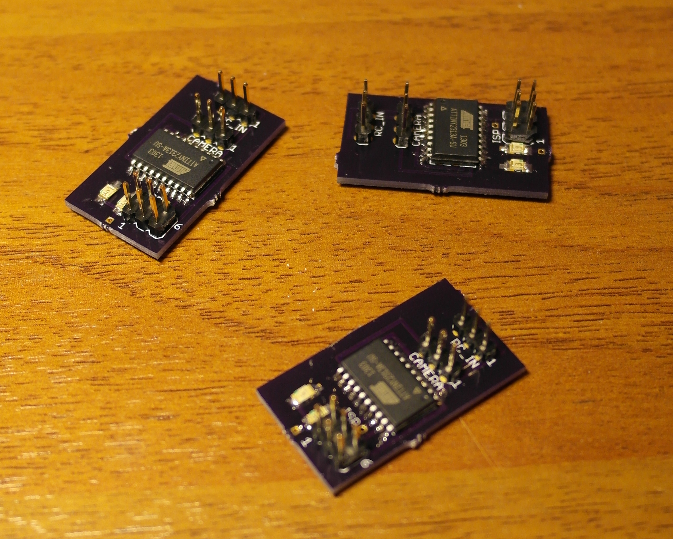
Shutter PCB’s
Display mount for Hitec Aurora
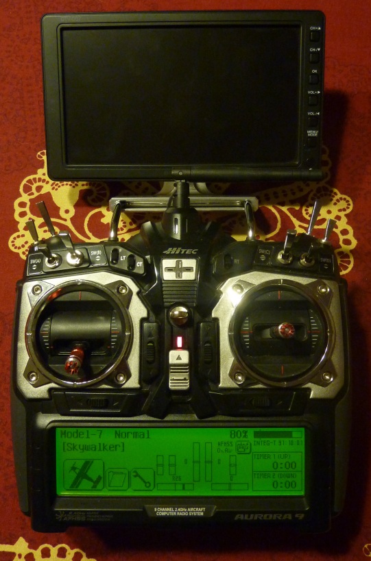
Monitor mount for Aurora
My usual setup when flying FPV is to have laptop running mission planner with image capture running. This works quite well, but forces me to stand in one place to see the picture, so I wanted something more mobile. I came across Procaster DTV-007 digital TV which at 45 € price is a real bargain. I wondered how to mount it with the controller, and my father came up with an idea to machine a mounting piece that would have a slot for the controller handle.
I drew the mount as two parts, first has a slot for Auroras handle and the second has t-slot for the display. Parts fix to each other with two screws. The part was machined in G-Tronic, where they optimized the part to a single piece. Overall, I’m happy with the results, the mount is very compact and stable in use.
Since there’s now machining files for this part, the design can be replicated easily if someone should need similar part.
Pictures:
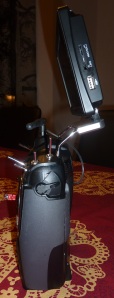
Side view
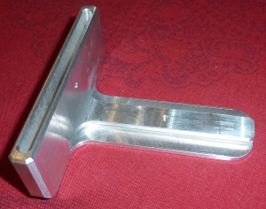
The part itself
Cad files:
Showing APM telemetry data on Hitec Aurora’s screen (revisited)
In my previous post I described building adapter which converts APM telemetry data to be shown on Hitec Auroras screen. Since then APM2 hardware has been released and some code changes made previous version unusable. I updated the hardware and software to support also APM2. I couldn’t get SPI transfer to work in APM2, but fortunately it has a spare serial port to use. The good thing is that now only three wires need to be connected to APM2 and nothing needs to be soldered.
APM1 is still supported, wiring instructions are in the previous post. When using with APM1, USE_SPI must be defined in main.cpp.
This version also includes support for showing GPS coordinates. Previously I thought it’s not really useful feature, but I changed my mind after searching for crashed plane in wintery forest in the light of the setting sun for a long time. Coordinates would have been useful after all. Time and Date are still unsupported since APM internal date format is yet to be decided.

Updated schematic

Connecting to APM2. Only three wires are needed.
Sources are uploaded to github: https://github.com/JanneMantyharju/apm-hss-emulator
Update 5.1.2013 – Error in schematic corrected. Added fet to power video transmitter after GPS lock has been acquired.
Update 7.1.2013 – Kind of a long shot, but if somebody wants to borrow me a Spectrum or Graupner system, I could modify the device to support different telemetry protocols.
Charging two 3S Li-Po packs at the same time
I updated my charged to balancing one a while ago, but for some reason I didn’t buy one of those new multichargers, which pack a number of separate chargers in to one device. I use two 3S battery packs in parallel configuration on my plane and I have three sets of those. After a day of flying, charging six 3S packs separately is a long and laborious task. Since my charger can handle 6S packs, I thought why not to make an adapter cable to charge two packs at once. Since all the cells are rated the same capacity, charging 2x3S packs in essentially same than charging one 6S pack.
The following cables were build:

Adapter to combine balancing leads from two 3S packs to one 6S connector

Adapter to wire to packs in series for charging
First adapter combines balancing leads from two packs to one connector. If you look closely, you can see that the ground wire is a little wriggly. When soldering the cable I did not think it all the way through and connected ground wires from both connectors together. When I connected the batteries, one of the ground wires vaporized with a loud pop. So be sure to leave second ground wire unconnected (pin 1 of the 2nd connector).
Second adapter is more obvious, it just connects the two packs in series. I suggest to number the battery connector which ground wire goes straight to the charger with number one and also the balancing connector which has ground wire connected as number one. These numbered connectors should be connected to same battery.
After connecting the batteries, set your charger to double voltage that the rated pack voltage (22.2v in this case) and charging current to the same as the rated charging current of the pack. It does not matter whether the packs are as empty or not, since the individual cells get balanced (although if there are big differences, balancing seems to take time at least on my charger). All that matters is that both packs have the same capacity and can handle the same charging current.
You can also make the same kind of adapters for 2S batteries, or even for the batteries more than 3S. The only limiting factor is that how many cells your charger can support at one time.

Simulated charging arrangement. Always use fireproof container when charging!
Schematics of the adapters:

Routing APM communications to Internet
I’ve been wondering, what would be the easiest way to route telemetry and commands from APM to Internet. Using 3G modem, would provide almost unlimited range (I know there has been some discussions about this in DiyDrones forum. Here in Finland the GSM network is very covering, but due the way the cellular towers are optimized, maximum altitude where the connection works is probably less than 200 m.)
In theory, list of required hardware is not long. One just needs to receive messages from APM and encapsulate them to UDP packets and send via 3G modem and vice versa. Unfortunately handling PPP communications is too large task for simple microcontrollers. I ended up using BeagleBoard for the sake of easy development and since I had one at hand. I realize that BeagleBoard (which essentially is full computer by itself) is an overkill, but it’s not very heavy and fits easily inside Maja’s fuselage. Basically any embedded system, capable of running linux and acting as an usb host would do. Maybe in the future I figure out some additional tasks for BeagleBoard to do.
Software
The software that handles the communications is a simple Python script. Since APM has no onboard configuration interface, the program fetches configuration at start-up (and every 5 minutes) from URL, given as parameter. Currently configuration consist on ground station IP-address and port. Since typically ground station is connected to internet with 3G modem, it’s IP-address is not fixed. Current address can be then updated to the configuration file and file uploaded to some known server.
When the script is running, it simply listens to serial port and when it receives valid MavLink packet, it sends to to ground station and vice versa. I made couple of fixes to UDP handling for APM Planner. By the time this text is published, modifications should already be included on the latest version (without the fixes, connection usually fails when Planner queries parameters from APM and expects to get those in a numbered order, but with UDP, packets may arrive in random order)
Hardware

Testing setup
Hardware wise setup is very simple. Beagleboard needs to be powered from 5v source. Due to 3G modem, power demand is very “spiky”, so regulator must have enough power output (big enough capacitor helps too). I connected APM telemetry port to BeagleBoard main serial port. Since Beagle has standard RS-232 levels and APM uses +3.3v logic, I used common MAX3232 driver between those. The downside is that console on BeagleBoard’s only easily accessible serial port must then be disabled. Be sure to do this only after you make sure, you can connect to Beagle via internet.
It’s also possible to use second serial port on Beagle. It’s however not enable by default and enabling requires compiling new kernel. Second serial port uses +1.8v logic, so level shifter is needed.
Setup
- Script to connect using 3G modem
- Script to bring up interface at boot and reconnect if needed.
- Disable console on serial port
- Place configuration file on known server
- Script to launch MavProxy at boot
Usage
- Connect ground station to net and check it’s ip
- Update ip to configuration file and upload it to specified server
- Power-up the plane and wait until it BeagleBoard boots up (Usually 3G modems have some kind of indicator light notifying when it’s connected. You can use this to check when the plane is ready)
- From APM Planner, select “UDP” as port and press connect (Plane must be sending data at this point)
- Enjoy!
Files
UAV Drone slideset

Example slide
A while ago I was asked to keep a small presentation about my plane in the workplace event. Here’s the slide set that I made for the presentation. Pictures can be borrowed to other uses, as long as you credit me.
- PDF-Slides: Maja presentation.pdf
- Keynote presentation: Maja presentation.key
Showing APM telemetry data on Hitec Aurora’s screen
Every now and then it’s good to pack light and leave the laptop at home and just enjoy flying. Running out of battery at inconvenient time is however a concern of mine. I just recently finished a project to display telemetry data from APM on Aurora’s screen. I’m not particularly proud of the technical side of the implementation, but this seems to work fine.

Aurora showing sensor data
Hitec’s Optima receivers interface with “Sensor station” via I2C, receiver being the master. APM has I2C-bus and it should support multiple masters, but I could never get it working reliably. My solution was to use ATMega88 to receive data via SPI from APM and relay the data to forward by answering queries send by the receiver. I originally considered tapping to xbee wires and decoding mavlink to get the data. This would however meant more work and I’m lazy.
Good things in this approach are that I can more flexibly get internal data from APM (not limited to data provided via mavlink messages) and the device can be used to extend APM (like add digital outputs etc). The downside is, that this requires changes to APM code and soldering couple of wires to oilpan, since it does not have connectors for SPI.
The circuit itself is really simple, just the avr, two resistors and a decoupling capacitor.

Schematic for interface board
The prototype is constructed to stripboard. Atmel ISP-connector is also used to connect the board to APM and the other connector is for the receiver. If there is interest, I can provide these devices constructed to decent pcb, with needed wires and programmed controller.

Prototype board
All the information that the sensor station suppors is emulated from the data from APM, even including fuel meter, which tells how much mAh are remaining from the rated capacity of the battery. The only thing that I haven’t implemented is GPS position and time, since they are not really useful without a map (except maybe when the plane is lost). One nice thing in Aurora is that you can rename temp and rpm labels. I’m using rpm-1 value for mAh’s used and rpm-2 for airspeed. Temp-2 is used to show the current throttle (0-100). Temp-3 and 4 are still left for some other data.
I’m really happy to get this working, since all the important data is available from transmitter screen with one glance and since the APM sends the data via xbee, this is a nice to have backup feature.
Sources are uploaded to github: https://github.com/JanneMantyharju/apm-hss-emulator
The code probably will have bugs on altitude and speed reporting, I haven’t yet tested it on flight due to bad weather. I’ll try to update it soon.
Read the comments from ReadMe.txt file. The included Makefile probably work only on OS X. I had trouble finding decent Makefile that could compile AVR code on commandline, using libraries from Arduino. There is hex file included ready to be flashed. When programming the controller, remember do disable the fuse that divides internal clock by 8. The code needs to run at 8MHz.
Connecting board to APM

Connections to “OilPan” (picture from APM wiki)
Three wires must be soldered to OilPan shield, marked in the picture above. Power, either 3.3v or 5v can be taken where you want, but one option is to solder I2C pinheader to OilPan shield and take power from those.
Please, drop a comment if you build this device. Patches to improve the code are also welcome!
[Update 10.5.2012] Code now supports APM2 and GPS coordinates. More info here!
